How to Create Instructions
This is a guide to create professional quality LEGO instructions. While I will go through all the steps, getting fast at creating these instructions will take time.
Introduction
I have wanted to create professional looking instructions for some of my LEGO creations, but have always been frustrated with the rendering quality of programs like LDraw and LDD.
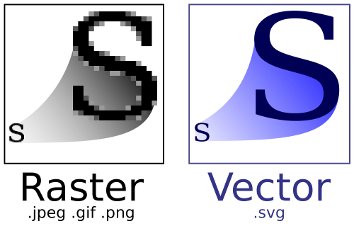
The core problem is those LEGO modelling programs give ‘raster’ images and not ‘vector’ images. Raster images are bitmap images and if you zoom in or print at standard quality you can see the individual pixels (or worse, jpeg artifacts). See Figure 1 for what I am talking about.
This guide will show you how to create professional, vector instructions using
a program called Inkscape and output them to .pdf.
I will be creating instructions for my nano-sized Nebraska State Capitol.
What You’ll Need
- A LEGO model
- Computer
- I would recommend a full keyboard and mouse
- Internet
- Inkscape available for free for Windows, Linux and Mac
- LEGO color palette
- Time
Application Setup
The first task is to set up Inkscape to work the way we need.
- Download and install Inkscape,
but do not open it yet
- I am using version 0.91 on Windows
- Copy/save the .gpl palette file
to
C:\Program Files\Inkscape\share\palettes- Note this path will differ on other operating systems
- Open Inkscape
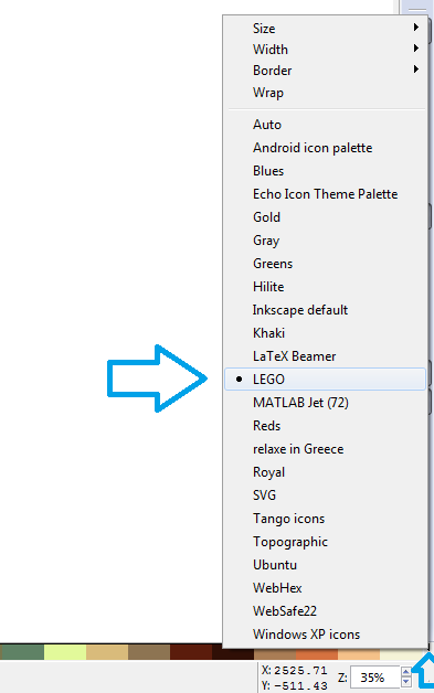
- Select the LEGO palette
- Click the little black triangle in the lower-right of the window
- Click on “LEGO” in the list, Figure 2
- If LEGO is not in the list, see step 2
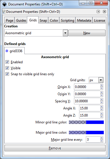
Document Setup
Now it is time to set up your instruction document. The steps here will make creating pieces in Inkscape fairly easy later.
- Press
Ctrl + Shift + Dor File -> Document Properties - Verify the “Document Properties” dialog is showing
- Click the
Gridstab at the top of the dialog - Change
Rectangular GridtoAxonometric Grid - Click
Newto see grid settings appear in the dialog - Set “Grid units” to
px - Set “Spacing Y” to
10.00000 - Set “Angle X” to
15 - Set “Angle Z” to
15 - Set “Major grid line every” to
3
Figure 3 shows what you should expect.
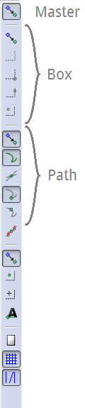
When we go to draw lines, we will want them to all line up. We also want the bricks to ‘snap’ into position when we move them. The easiest way to do this is to toggle the snapping tools appropriately.
- Locate the snapping tool bar (on the right side of your window by default)
- Disable all of the
boxsnapping - Enable the first two and the fourth
pathsnapping
Everything should look like Figure 4.
If you need to turn off snapping temporally, click the topmost ‘master’ button
or press the percent key: % (or Shift + 5).
I have found that if you snap to path intersections or to smooth nodes, your CPU has to work very hard (because of all of the round studs we will be creating).
First Piece
Now it is finally time to start doing something that looks like a LEGO! We will start by creating a 1x1 brick (regardless of whether your model needs one).
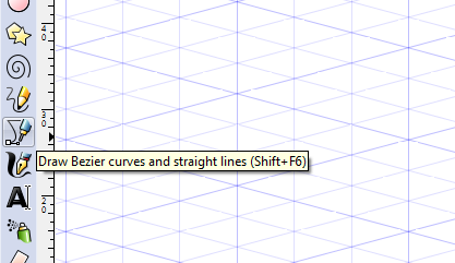
First Shape
- Zoom in until the grid lines stop dividing and you can see a few ‘major diamonds’ grid-lines
- Click on the
Draw Bezier curves and straight lines (Shift + F6)button
Figure 5 shows the zoom level and tool bar button
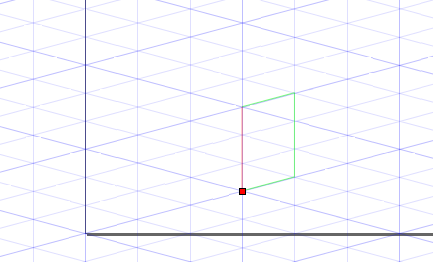
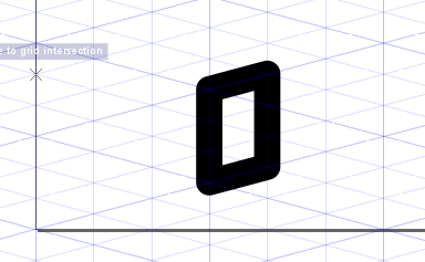
Draw the right face of a 1x1 brick using the Bezier tool by clicking 4 points:
- Click on the bottom of a major grid-line
- Note you only have to get close to the grid-line intersection because of snapping
- Click next up and to the right at the next grid-line intersection
- Make your third click 3 minor (1 major) grid line up
- The fourth point should be three minor points above your first point
- Finally click the original point to close the shape
Figure 6 shows what you shape should look like right before closing it (after step 1.4) and Figure 7 shows what it may look like when it is done. If Figure 7 does not match completely, do not worry; we will fix that soon.
If you have not saved, please do so now (as an .svg file). Save often!
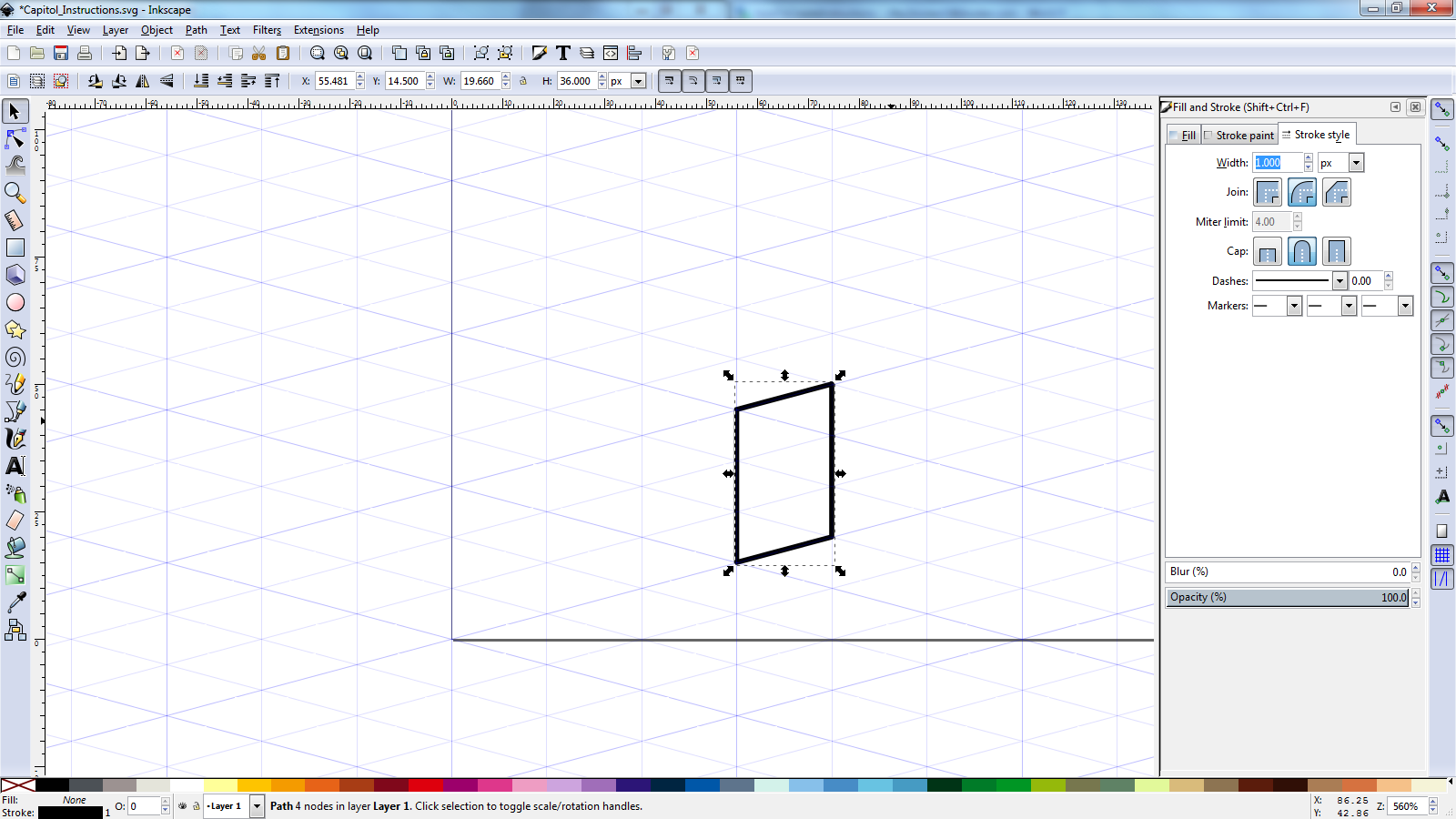
Object Setup
- Click on the
Select and transform object (F1)tool button- I simply call it the “Object” button
- Click on your object to select it
- Press
Ctrl + Shift + For select Object -> Fill and Stroke… from the menu - Select the
Stroke Painttab- If
Flat Colorbutton (looks like a solid blue square) is not selected, press it - Click the
Wheelbutton- You may use whichever color selector scheme you prefer
- Select black color (RGBA:
000000ff) - Make sure alpha (
A:) as at 100% - Make sure Blur is at
0%
- If
- Select the
Stroke styletab- Set the Width to
1.000px - Set the join to the middle/smooth one
- Set the cap to the middle/round one
- Set the Width to
Your object should now look like the one in Figure 8
Tool Setup
- Double click on the Bezier path tool button
- See the preferences dialog appear on Tools -> Pen page
- Check
Last used styleradio button (Figure 9) - Close the preferences dialog
- Select the object button
- Select your only object (if needed)
- Click on the “Bright Blue” color on the palette
- Observe your brick is now blue with a black border
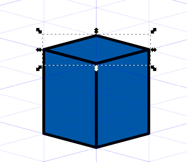
Draw the Other Sides
Now it is time to draw the other three (visible) sides of this 1x1 brick.
- Select the draw bezier tool
- Draw the left size as you did the right size
- Click on the lower left corner of your existing shape to start
- Then draw the next three points
- Remember to click the first point again to close the shape
- Note that solid lines overlap
- Draw the top of the brick
- Click on each to the ‘top’ three points that bound your existing shapes
- Then click on the minor grid-line above
- And click the first point again to cap it off
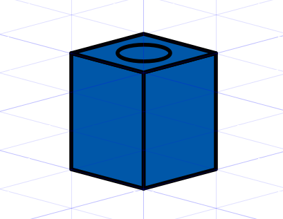
You should now have the three shapes that form a 1x1 brick (without the stud) as seen in Figure 10.
Stud
Now it is time for our first stud. This part is the trickiest. I have found what looks good (or accurate) zoomed in does not look when you look at the model as a whole.
- Disable snapping by clicking the first/master snap tool button
- Select the circle tool (
F5) - Draw an oval/ellipse over the top of your brick
- Do not worry about getting it just right yet
- Select the object tool and select your oval/ellipse
- Use the resize handles (diagonal arrows at the corners) to make the the oval
make the oval smaller than the center of the top of your brick
- If you click the object twice, these will turn into rotate handles
- If that happens, simply click the center of the object again
- You can use the alignment tools to center your shape
Ctrl + Shift + Aor choose Object -> Align and Distribute from the menu- Set “Relative to:” to
First Selected - Click the top shape of your brick
- Shift click the oval
- Click the two center buttons:
Center on vertical axisCenter on horizontal axis
- After you get the oval much smaller than your top-of-brick shape,
set its stroke size back to
1px
Figure 11 below shows you approximately what size the ‘stud base’ should be.
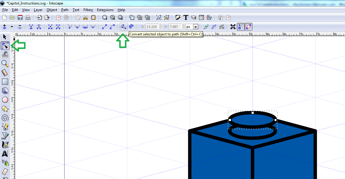
Now to finish the stud.
- Select the stud object
- Hit
Ctrl + dto duplicate (or right click -> duplicate) - Hold down
Ctrland click and drag the (duplicated) oval upward- Drag it until it just crosses the topmost corner of the brick
- Duplicate that moved oval
- Click the
Edit Paths by Node (F2)tool - Click the
Convert selected object to path (Shift + Ctrl + C)- See Figure 12
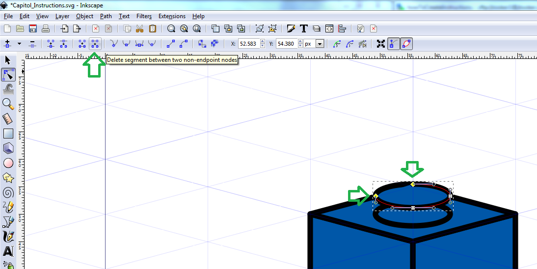
- Repeat for the first/lowest oval
- On the top oval, select top and left (or right) node, then
Delete segment between two non-endpoint nodes- See Figure 13
- Select just the topmost node (of the topmost oval) and delete it
- Repeat on the bottommost oval
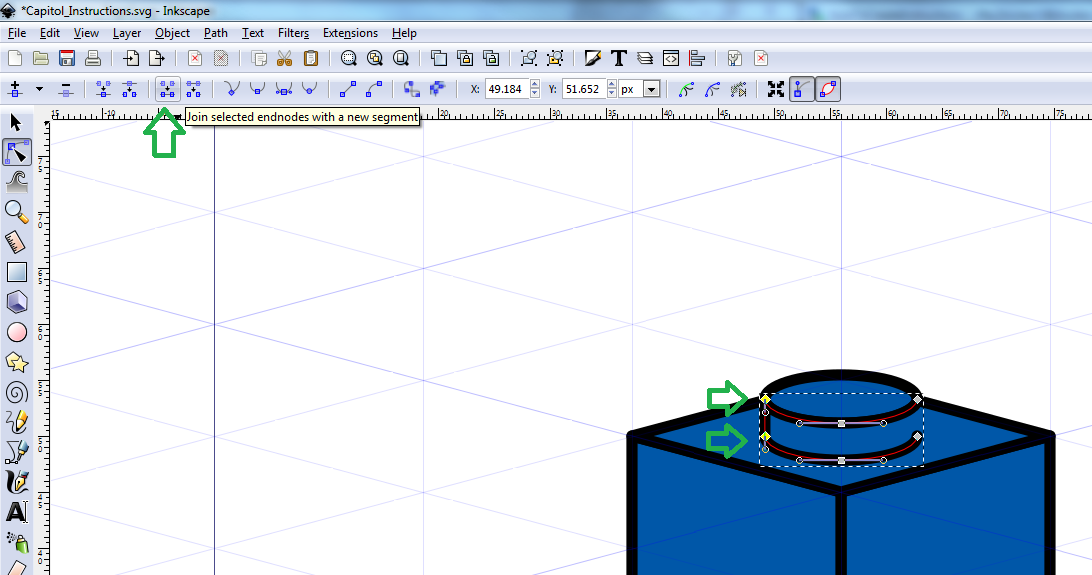
- Select both ‘half ovals’ and click
Ctrl + kto make them the same object - Select the leftmost two nodes, then join the paths
- See Figure 14
- Repeat for the two rightmost nodes
- Now on the Fill and Stroke Dialog (
Ctrl + shift + F) choose theFilltab - Change the fill color all black (RGBA:
000000ff)
Your 1x1 brick should look like the one in Figure 15.
Select all (click and drag around the whole thing), then press Ctrl + G
to group all objects (or right click and group).
Also turn snapping back on.
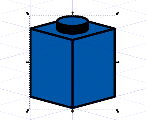
Before continuing, I’d recommend duplicating a dozen or two of these,
placing them next to each other and making sure they look good zoomed out.
Hint: you can duplicate multiple at once.
Snapping should make positioning them easy, especially if you drag from a
corner of the brick.
If the stud does not look good to you, delete the copies, ungroup the original
(Ctrl + Shift + G) and resize the stud.
Remember to make all paths 1px wide when you are done.
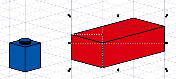
2x4 Brick
Now we will make a 2 x 4 red brick.
- Select the Bezier tool
- Make the long side of a 2x4 brick using the guides
- If you forgot to turn snapping back on, do so now
- It should be 3 minor (1 major) guide line high and 4 wide
- Make the narrow side
- And finish with the top (no studs yet)
- Select all objects and click
Redin the palette area
Your unfinished brick should appear like the one in Figure 16.
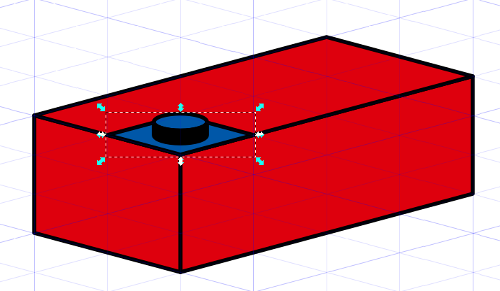
Now for the studs.
- Select your blue 1x1 brick
- Duplicate it (
Ctrl + D) - Drag the duplicated copy elsewhere
- Ungroup the copy (
Ctrl + Shift + G) - Delete the left and right sides (but not the top or stud)
- Select the top side and stud objects
- Group them (
Ctrl + G) - Drag your object to the bottom corner of the top red object
- See Figure 17
- Duplicate the blue object and move it to the left and up to fill the leftmost corner
- Select both stud object, duplicate and cover more area
- Repeat until the 2x4 red brick is covered with 8 stud objects
- Make sure you are using snapping
- See Figure 18
Ctrlclick and delete each blue diamond shape (not the studs)- Tip: you can
Ctrl + Shift + Clickto do all your selecting at once - If you delete something you should not, just undo and try again
- Tip: you can
Ctrlclick each top-of-stud object (only blue left)- Click the
Redpalette
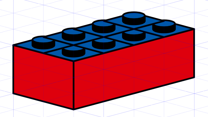
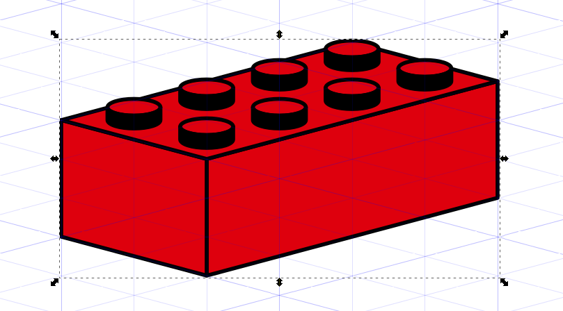
Now your red 2x4 brick is complete. Select all the red brick objects and group them. This should look like Figure 19 below.
Create Your Inventory
Now that you have the basics, create an inventory of brick you will need. It is up to you whether you create all the different types you need now or as you go, but I’ll create the ones I need now.
A couple notes:
- Plates are just like bricks, but only one minor grid-line high.
- Tiles are just like plates, but no studs.
- Slopes are a bit more difficult, but not by much.
- Other bricks are more complicated
- Use the Bezier tool to create the paths you need
- Turn of snapping as needed
- Use the ‘transform’ handles (with object tool, click twice - non-corner handles) for vertical features (e.g. SNOT brick studs)
I will be creating the bricks I need for my Micro (Nano) Nebraska State Capitol.
Capitol Inventory
- 6x Black Plate 1 x 4
- 1x Black Plate 2 x 3
- 1x Black Plate 2 x 12
- 2x Black Plate 6 x 8
- 1x Black Plate 6 x 12
- 4x Black Tile 1 x 6
- 4x Black Tile 1 x 8
- 20x Dark Green Plate 2 x 3
- 4x Light Bley Plate 1 x 1
- 4x Light Bley Plate 1 x 4
- 1x Light Bley Tile 1 x 1
- 1x Light Bley Tile 1 x 2
- 7x Light Bley Tile 1 x 4
- 3x Tan Brick 2 x 2
- 1x Tan Brick 2 x 2 round
- 2x Tan Plate 1 x 1
- 8x Tan Plate 1 x 2
- 8x Tan Plate 1 x 3
- 8x Tan Plate 1 x 4
- 3x Tan Plate 2 x 2
- 13x Tan Plate 2 x 3
- 1x Tan Plate 2 x 4
- 10x Tan Plate 1 x 2 with Jumper
- 10x Tan Tile 1 x 1
- 4x Tan Tile 1 x 2
- 1x Blue Plate 2 x 2 round
- 1x Copper Brick, Round 2 x 2 Dome Top
Figure 20 shows one of each of these parts. You will need to use white or light gray for the borders of black pieces.

For the jumper plate, I took a stud apart and aligned the ‘bottom part’ to the center of the top-of-plate object, then I aligned the actual stud to that.
For the round bricks, I grouped the ‘square’ parts in the background for alignment/snapping and only removed them after I positioning them; you can see these light blue shapes in Figure 20.
I’ve found working with every piece at once can slow down your machine. You may wish to just add pieces as you need them.
Make sure to group all the shapes of your pieces.
Instructions Steps
It is finally time to create all the instruction images. We will first create all images, then worry about positioning/labelling them.
First Step Image
- Find your ‘lowest’ or ‘base’ pieces
- Move/duplicate them to the right place
- Make sure to have snapping on
- Use
Page UpandPage Downkeys to adjust what objects overlap others - I would suggest doing the ones in the back/furthest away first to minimize layering fixes (when you duplicate an object the copy is on top)
- Be aware of the
Flip selected object horizontalbutton on the object tool
- Select all of those pieces and group them
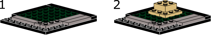
Figure 21 shows the first level of the capitol.
Second Step Image
- Duplicate your first image and move the copy down below the original
- Leave enough space to put the next layer of pieces on
- Position each other piece on top of the original layer
- You can save space/computer resources by deleting hidden studs (the ones on the first parts that are now/will be covered up); it is tedious but often worth it for baseplates and the like
- You can also delete whole hidden pieces for the same reason
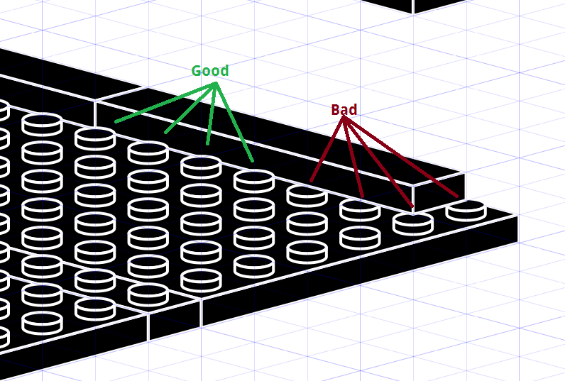
- If you are not covering a whole layer, you’ll need to break the lower
part images apart and use
Page Upto place the lower bricks studs above the higher layer’s object; see Figure 22
- Once you have all pieces for this step positioned, group your object
Rest of the Pieces
- Duplicate (and move down)
- Moving is where your CPU will chug due to all of the objects, just be patient
- Save often
- Add new pieces
- Group
- Repeat
Tip: you can draw boxes around ‘sub-steps’
Tip: you can add arrows to the end of paths in the Fill and Stroke's
Stroke style tab under the Markers: setting.
Tip: to place pieces on jumpers:
- Duplicate the piece three times.
- Then snap the first and second copy to the left and right (respectively) of where you want the centered piece
- Group those two
- You can give them a diffrent color so they stand out
- Use the alignment tools (
Ctrl + Shift + A) to align the origional between the grouped copied - Delete the two-copies group
Figure 23 has all the images we need for the capitol’s instructions.

Completing the Instructions
Now that we have the source images, it is time to put it all together.
The main goal is to arrange these images (groups in the .svg file) on to
multiple page-shaped .svg files.
We will then save these page-shaped file as .pdfs and merge them all.
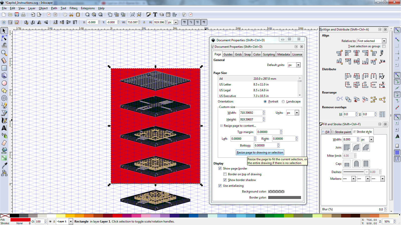
My instructions only have 8 images, but each is fairly wide and complicated. Thus, I will put 4 on each page. My pages are 8.5” x 11”.
- Make an 85px x 110px, borderless rectangle object
- Use the object tool to move and stretch it to cover one page-worth of
instruction images
- Hold down
Ctrlwhen resizing to keep the 8.5:11 ratio (or whatever your page size is) - When you get close, use the
Endkey to send it behind your images
- Hold down
- Press
Ctrl + Shift + Dto bring up the document properties dialog - With your rectangle selected on the
Pagetab, click theResize page to drawing or selectionbutton- Expand
Resize page to content...if needed - See Figure 24 below
- Expand
- Close the dialog
- Delete the page-size rectangle
- Do any final arrangements
- Add numbers using the text tool and align them with each image
- File -> Save as
instructions page 1.svg(or similar) - File -> Save a copy as
instructions page 2.svg - Delete all images not within the page boundary
- File -> Save a copy as a pdf:
instructions page 1.pdfor similar
- Close Inkscape and open up
instructions page 2.svg - Remove all images in the page area and move the next set into the page area
- Save
- Save a copy as page 3 (if needed)
- Delete all images that do not fit on the page
- Save a copy as
instructions page 2.pdf - Save and quit
- Repeat these steps until you have a set of
.pdfwith each image
Now that you have a set of .pdf files, each one page large, we need to
concatenate them into a single document.
The only way I have used is PDFMerge;
it is free (up to 15 MB files) and online.
- Go to http://www.pdfmerge.com/
- Choose each file (I have two)
- Click the
Merge!button - Watch your download start soon, likely named
merged_document_1.pdfor similar - I would rename it
And that is it. Now you have a professional, print-quality LEGO instructions
document. When printing the .pdf, make sure to resize to your printing page’s
size.
See Capitol_Instructions.pdf for my finished product.
LEGO, LEGOLAND, DACTA, DUPLO, PRIMO, FABULAND, SCALA, TECHNIC, MINDSTORMS, and ZNAP, etc. are trademarks or registered trademarks of The LEGO Group, which does not sponsor, authorize, or endorse this site.